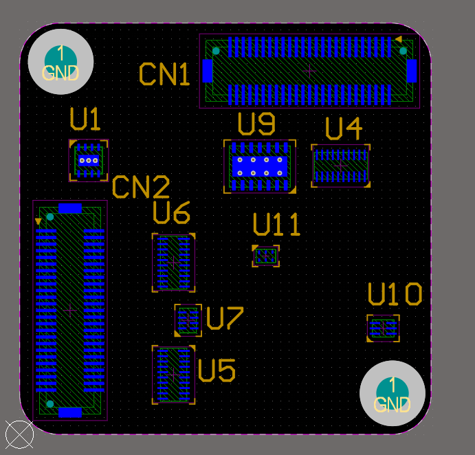
If your board are 2-layer, there will be no inner layer(G1,G2,G3.) Please make sure you have the clear outline in mechanical layer. In the General Setting set the precision to 2:5 (0.01 mill resolution) Select File -> Fabrication Outputs -> Gerber Files.
#Altium designer pcb layer software
Open your .PCB design files on Altium designer software If you have corrections or find errors, please email support.ġ. Use your judgment and always verify your designs meet our capabilities to prevent design defects that could affect your boards. Note, these files are not exhaustively validated or guaranteed by JLCPCB. JLCPCB-4-Layer-Stackup.zip JLCPCB-6-Layer-Stackup.zip Our Kind customer has provided loadable DRC rule and Stackup files for our multilayer services. Top assembly: should show the shape of the components and mechanical dimemensions.How to export Altium PCB to gerber files Design Rule Setup The solder stop is the thin coating layer that makes the pcb green (usually), it’s function is to prevent accidental solder bridges and shorts during the soldering process. Top solder: this indicates where the solder stop mask goes on your pcb. It is used to produce stencils for solder paste deposition. Top paste: this layer designates where the solder paste should go on your pcb before placing any SMD component (usually done by pick and place machine). Top layer: this defines where the copper goes.
#Altium designer pcb layer pdf
You can put the designators on this layer so that you can still produce a pdf output with a “map” for what goes where on the board. Maybe your board is too small to print designators or you want to save some buck by not having silk screen. If you could clarify these questions for me, I would greatly appreciate it.ĭesignator: layer used to put component designator in case you don’t want or you can’t print them as silkscreen. The top layer and the top solder layer look identical (except for the color of course) so why do we need both? the designator, the top layer, the top paste, the top solder, and top assembly). For example, I know that the top overlay is for text (the silkscreen), the component center layer is for providing an origin/zero point/reference point for the component, the top courtyard is for declaring that "this component needs this much clearance to ensure that it doesn't collide with other components".īut I am not really sure what the other layers are for (i.e. Some of them, I already have a general idea on. I was wondering if you could give a description of what each of these layers are, what their purpose is, how it is linked to the actual, physical pcb, etc. In this link, you will see a design, and you'll see the various layers that make up that design.

Would you please share your knowledge on these layers? I have posted some images here as a reference. However, Altium seems to have many more layers than what is actually physically present on a pcb. The soldermask is applied on top of the copper, and the copper can form the signal/ground layers. This material is what gives a pcb its distinct color. There is also the soldermask which is a dielectric material used to ensure that different pcb traces won't touch each other.

For a physical pcb, I know that there is the silk-screen layer (which would be the top overlay layer in Altium) and this is where text is written and graphics is shown. I am somewhat familiar with how a pcb is fabricated, however I am not quite sure how the various layers in Altium corresponds to the actual layers of a pcb. For instance, there is the "top layer", "top solder", "top paste", etc. However, I find that I am confused as to how the pcb design process works in terms of the various layers that are used in Altium. Hi all, I am new to PCB design and I am learning to use Altium designer.


 0 kommentar(er)
